-
Products
New Products
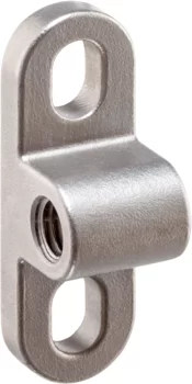
- Locators with bore hole, for spring plungers
- Locators smooth, for spring plungers
- Holders for spring plungers
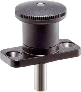
- Index Plungers Mini Indexes with mounting flange
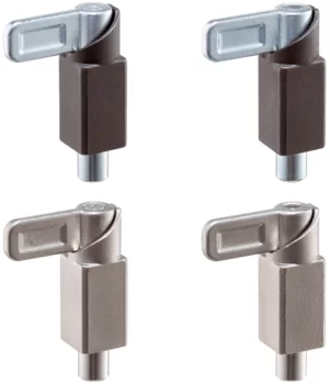
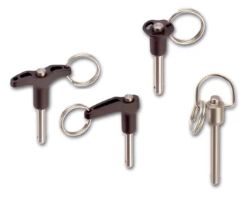
- Index Plungers with locking mechanism push-lock
- Index Bolts threadless, weldable
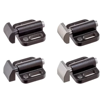
- Spring Push Plungers with mounting flange, horizontal
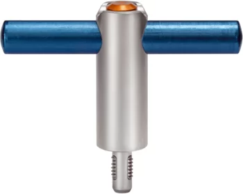
- Threaded Lifting Pins self-locking, with handle
- Bedding Supports
- Flat Knurled Nuts DIN 467
- Flat Knurled Thumb Screws DIN 653
- High Knurled Nuts DIN 466
- High Knurled Thumb Screws DIN 464
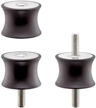
- Rubber Metal Buffers waisted
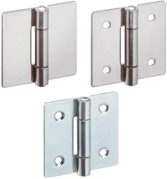
- Hinges
- Hinges
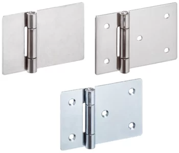
- Hinges elongated on one side
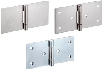
- Hinges elongated on both sides
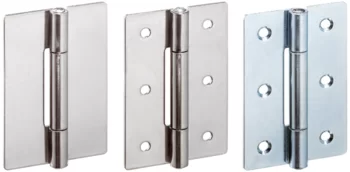
- Hinges long version
Further Information:Product Groups- Forestry Tools
- Accessories
- Promotional Boxes
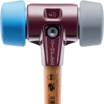
- SIMPLEX soft-face mallets, cast iron housing
- SIMPLEX soft-face mallets, reinforced cast iron housing
- SIMPLEX soft-face mallets, aluminium housing
- SIMPLEX soft-face mallets, cast iron housing, with "Stand-Up"
- SIMPLEX soft-face mallets, cast iron housing, 50:40
- SIMPLEX soft-face mallets, aluminium housing, 50:40
- SIMPLEX soft-face mallets, cast iron housing, extra short handle
- SIMPLEX soft-face mallets, cast iron housing, with "Stand-Up", extra short handle
- BASEPLEX soft-face mallets
- SIMPLEX sledge hammers, cast iron housing
- SIMPLEX sledge hammers, reinforced cast iron housing
- SIMPLEX sledge hammers, cast iron housing, with "Stand-Up"
- SUPERCRAFT soft-face mallets
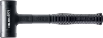
- BLACKCRAFT soft-face mallet
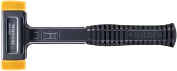
- SECURAL soft-face mallet
- SUPERCRAFT sledge hammers
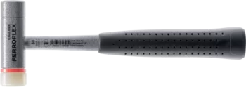
- FERROPLEX Combi Hammer
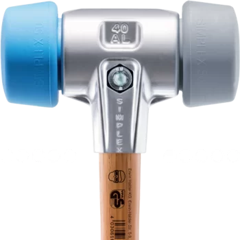
New Items- SIMPLEX soft-face mallets, 50:40 TPE-soft / TPE-mid; with cast iron housing and high-quality wooden handle
- SIMPLEX soft-face mallets, 50:40 TPE-soft / TPE-mid; with aluminium housing and high-quality wooden handle
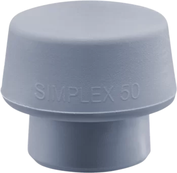
- SIMPLEX insert, 50:40 TPE-mid, grey
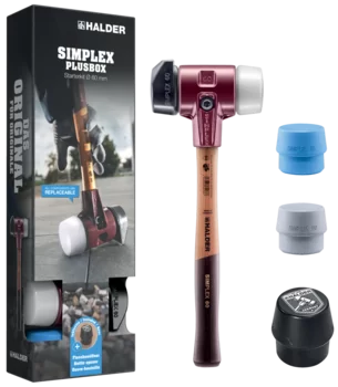
- SIMPLEX Plus Box Starter Kit SIMPLEX soft-face mallet D60, rubber composition with "stand-up" / superplastic as well as one TPE-soft and one TPE-mid insert plus bottle opener
- SIMPLEX Plus Box Starter Kit SIMPLEX soft-face mallet D80, rubber composition with "stand-up" / superplastic as well as one TPE-soft and one TPE-mid insert plus bottle opener
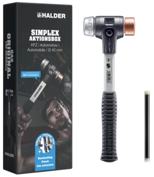
- SIMPLEX Promotional Box Automotive SIMPLEX soft-face mallet D40, copper / soft metal plus puncher
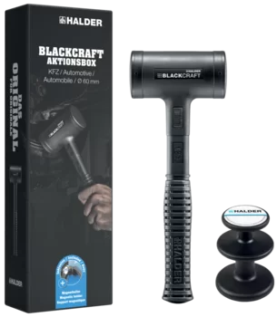
- BLACKCRAFT Promotional Box Automotive BLACKCRAFT soft-face mallet D60 plus Magnetic Holder
- Promotional Box Dreamteam Door and Window Construction SIMPLEX soft-face mallet 50:40, TPE-soft / TPE-mid and SECURAL plus soft-face mallet
- Service
- Newsroom
- Company
- Contact
22123.0116 - Index Plungers
with sensor
Index plungers are used for indexing bores.
The index plunger with sensor makes it possible to monitor the indexing position of the indexing plunger. When it engages, the sensor already switches after 2/3 of the indexing distance l2. In addition to the electronic signal, the switching status is indicated directly on the sensor via an LED.
This article 22123.0116 - Index Plungers with sensor / with knob and locking (d1 -0.02 -0.05: 16 mm, d2: M24 x 2 mm, l2 min.: 20 mm) is one variant of the article group Index Plungers with sensor (EH 22123.)


- with knob and locking – picture 2
- d1 -0.02 -0.05: 16 mm
- d2: M24 x 2 mm
- l2 min.: 20 mm
- d3: 33 mm
- l1: 85 mm
- l3: 38 mm
- l4: 18.5 mm
- WS: 27 mm
- Spring load1) F1: 13 N
- Spring load1) F2: 54 N
- Operating temperature range min.: -25 °C
- Operating temperature range max.: 75 °C
- Weight: 313 g

Material
Body
- Stainless steel 1.4305
Locking pin
- Stainless steel 1.4305, nickel-plated
Knob
- Thermoplastic PA 6, black, dull
Cable
- Thermoplastic PUR, black
Magnet
- Permanent magnet
Sensor
- Thermoplastic PA 6, black, dull
Lock nut
- Stainless steel A2 (ISO 8675)
Notes
Knob not removable.
Assembly
The enclosed separate sensor and sensor clip can be mounted with the enclosed Allen key. The derivation direction of the sensor cable can be determined individually.
- Push the sensor into the side of the sensor clip.
- Tighten the internal hexagon screw of the sensor with light hand force (max. 0.1 Nm).
- Clip the sensor clip into the annular groove of the index plunger in any position.
- By turning the sensor clip, the sensor cable's derivation direction can be adjusted.
Note:
To avoid interferences, no magnetic fields should act on the index plunger.
Operation
When using locking index plungers, the knob is pulled-out, turned 90° and secured by a notched catch (when locking pin should not overhang).
RoHS compliant
Compliant according to Directive 2011/65/EU and Directive 2015/863.
Does not contain SVHC substances
No SVHC substances with more than 0.1% w/w contained - SVHC list [REACH] as of 27.06.2024.
Does not contain Proposition 65 substances
No Proposition 65 substances included.
https://www.P65Warnings.ca.gov/
Free from Conflict Minerals
Contact Form
Information Material
Information material Standard Parts Information material Workholding Systems Information material Aviation ProductsNews
Have a look to our current new parts:
Threaded Lifting Pins with handle Bedding Supports Spring Push Plungers Accessories for spring plungers Index Plungers / Index Bolts Damping Elements Hinges Knurled Nuts / Knurled Thumb Screws